Anne Carpenter
Not every image you capture on your microscope is suited for quantification, no matter how nice they may look. Even though you might not notice any problems by eye, the tips outlined here for acquiring and storing images can improve the quality of data derived from digital image analysis. These tips are a bit CellProfiler-centric but generally applicable to any quantification you might do.
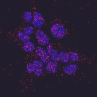
Raw Image
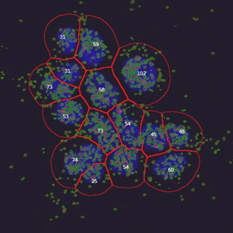
Corrected image, using a CellProfiler image analysis pipeline for spot detection
1. Lossless file formats: please, no JPG!
- Some methods of file compression sacrifice image quality (“lossy”) and should be avoided for automated image analysis if at all possible (e.g., JPG/JPEG). Other file compression formats retain exactly the original image information but in a smaller file (“lossless”) so they are perfectly acceptable for image analysis (e.g., PNG, TIFF, GIF). Uncompressed file formats are also fine for image analysis (e.g., BMP). Wikipedia: Image file formats can tell you more.
- Already saved your images in a lossy format? Sorry, but there is no salvaging the loss of data; converting them to a lossless format now provides no benefit.
2. Proper exposure time: avoid saturation and lack of dynamic range
- Typically, you want to keep image acquisition conditions constant across an experiment. For example, don’t use automatic exposure times or change the lamp or filter settings part way through collecting a large image set if you aim to quantitatively compare signals across the set of images.
- Be aware that microscope lamps often take time to warm up, so that a 1 second exposure is not guaranteed to yield the same response, depending on how long it has been since the lamp turned on, or how long it has been since the bulb was changed. LED light sources tend to be more consistent and are preferred.
- Set the exposure time such that the resulting images use as much of the dynamic range of the camera as possible, but without saturating any images. Aiming for your image maximum to be ~50-75% of the dynamic range is a safe bet, allowing for some images in the set being brighter than average without becoming saturated. If you expect one sample in your experiment may be brighter than others (a positive control for example), you may want to use it to determine your exposure settings to decrease the likelihood of ending up with saturated images. Most microscope software allows you to see a histogram of pixel intensities – you want the histogram to fill most of the available pixel intensities (along the X-axis, usually: see Figure), but you do not want any pixels to reside at the highest intensity value of the camera – you do not want a spike at the right-hand side of the histogram. This awesome article will tell you more about dynamic range and image saturation: Fluorescence microscopy – avoiding the pitfalls Claire M. Brown, J. Cell Sci. 120:1703-1705.
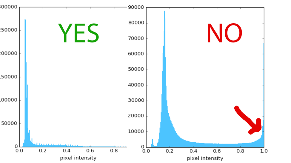
When viewing a typical test image’s histogram, the maximum pixel intensity should use ~50-75% of the range (left), leaving a bit of room if some of your samples or fields of view are brighter. You should NOT see any pixels piled up on the right, at the maximum of the range – the intensity of pixels there will not be accurately recorded
3. Bit depth: Be sure your image file’s bit depth suits the camera’s pixel intensity range
- Bit depth describes the number of data bits available to represent the intensity value of a single pixel. It is also known as bits per pixel (bpp). In other words, a file format’s bit depth tells you the number of separate grayscale intensity values (graylevels) that are allowable by the file format:
- 8-bit images have 2^8 available pixel intensities, with a range of 0-255
- 12-bit images have 2^12 available pixel intensities, with a range of 0-4095
- 16-bit images have 2^16 available pixel intensities, with a range of 0-65535
- Many microscope cameras capture 8-bit images and store them in an 8-bit file format. All image-viewing software can display 8-bit images.
- However, many microscope cameras capture 12-bit images, which contain finer detail (in terms of graylevels) than 8-bit images. 12-bit file formats are rare and incompatible with most software, so the two options are usually to save the image in a 16-bit format or an 8-bit format.
- Saving 12-bit image data in a 16-bit file format is generally preferred because it has the advantage of not losing any fine detail in your image data. However, it can be inconvenient because most image-viewing software on your computer will display such images as very dark (or they might fail to recognize or open 16-bit format at all). Don’t worry: all the information in the image is actually there! You will just need to choose particular software to view the images instead of your operating system’s default viewer (FIJI/ImageJ is a great choice for this). Alternately, you can contrast-stretch the images (just for viewing purposes! Do not save them after doing so).
- Saving 12-bit image data in an 8-bit format causes some of the fine detail in the image data to be lost and is thus usually unsuitable for quantifying experiments requiring sensitivity. However, it does allow you to readily open the images in all image-viewing applications.
- By default, for viewing, CellProfiler contrast-stretches images (switching the “Normalized” dropdown menu of an image to “Raw” will show you the raw images instead). This is because the 12-bit saved in 16-bit situation is so common; plus, if you’ve followed the rule of only using ~50% of the dynamic range (see tip #2!) your images will appear a bit dark if presented raw. But do not worry! CellProfiler analysis uses the actual intensity values, not the stretched ones. For image analysis of 12-bit images stored in a 16-bit image file format, use the Rescale Intensity module according to the instructions in its help.
4. Grayscale vs. color images: save whatever you like!
- Most microscope cameras capture grayscale images. First, a definition: grayscale images have many shades of gray. Although in plain English we often call such images “black-and-white” images, that term can be confusing so you might like to avoid it. Here is why: in the context of image analysis, there is a thing called binary images that literally have only two colors: black and white (represented as pixels with values 0 and 1 respectively).
- Typically microscopes image each channel (wavelength) as a separate grayscale image, although sometimes the software combines channels to create a pseudo-colored image (for example, displaying three channels as “RGB”: red, green, blue).
- Save your images however you like! CellProfiler has modules (Gray To Color, and Color To Gray) that can combine and separate the individual channels as needed for an analysis, so you need not manipulate your images to combine or separate channels before running a CellProfiler image analysis pipeline. You can also use the Align module if the separate channels of an image do not align well with each other. (Note: this only applies to experiments with 3 channels or fewer. If you have more than 3 channels, you should save each channel separately!)
- But please, do not save images with scale bars (rulers) or other annotations on top if you intend to quantify the images.
5. Magnification/resolution/binning: make good choices
- In general, choosing a higher-magnification lens produces higher-resolution images that yield better-quality image analysis results. However, choosing a lower-magnification lens offers a larger field of view so that you can image more cells per image, which can improve the statistical robustness of your results. You should balance these competing demands to suit your biological assay system.
- Binning is an important setting on the microscope’s camera that can impact image analysis. Binning essentially decreases the resolution of the images but increases the signal to noise ratio and speed of image acquisition. It does this by combining light from several nearby pixels (often 2×2 = 4) into a single pixel. Binning therefore can be helpful if you have dim samples, but you may want to avoid it if the objects you care about are very small (only a few pixels across) since you could lose important information about their size and shape.
6. Illumination/background variation: correct if you can
- Although illumination sources that use fiber optics are more spatially consistent than lamps, images from both can nonetheless be subject to uneven illumination (e.g. more bright in the middle and darker towards the edges, known as vignetting).
- Many microscopes have an option to correct for uneven illumination in the field of view by a method called white-referencing (or white-shading, or background correction). In brief, an image of a “blank” field of view is collected at the time of the experiment (no biological sample is present, but instead, ideally, a uniformly fluorescent sample using the same dyes as in the assay). You would hope that such an image would have precisely the same intensity values across the entire field of view, but often there is a spatial pattern. To correct each image of biological samples in the experiment, the pattern seen in this white-referencing image is subtracted from each image. This is described as a priori illumination correction in this tutorial on the ImageJ website.
- Even if you carry out white-referencing, illumination correction may still be necessary – particularly if you are doing a large-scale experiment where precise quantification is needed. CellProfiler has many retrospective methods of illumination correction for this purpose. See the help for the Correct Illumination Calculate module for more information, as well as our paper on the topic.
- Molecular Probes/Invitrogen sells a 96-well microplate coated with fluorescent beads (TetraSpeck Beads) for spot QC checks and to check the x and y registration of different wavelengths.
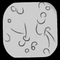
Image before illumination correction
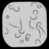
Image after illumination correction. Usually illumination problems are not this obvious, yet they can dramatically influence intensity measurements.
7. Plate types for imaging
- If you are doing a high-throughput experiment in a multi-well plate, be sure the plates are compatible with microscopy per the vendor.
- For fluorescence microscopy, black plates are typically used. Clear plates can cause problems with laser focusing mechanisms of the microscope (per Meg Bliss-Moreau at Broad’s screening facility).
- Here are some plates we commonly use at Broad:
| Product | Bottom Thickness | Vendor Order Number | Fisher Order Number |
| Corning 384-Well Clear Bottom Black or White Polystyrene Microplates | 0.64 | 3712 | 07-200-650 |
| Corning CellBIND™ 384 Well Flat Clear Bottom Polystyrene Microplates, with lid, sterile, 10/bag | 0.64 | 3683 | 07-201-015 |
| Corning™ 96-Well Clear Bottom Black or White Polystyrene Microplates | – | 3603 | 07-200-565 |
8. Brightfield/histology images
- While for most fluorescence markers the amount of fluorescence is linearly related to the amount of material present, this is not true for absorbance-based stains such as hemotoxin/eosin (H&E). Whenever possible, avoid absorbance-based stains and use fluorescence markers instead, if you aim to quantify the amount of stain present. It may be possible to obtain accurate metrics such as cell counts, though.
- Sometimes “defocusing” (taking images a few microns up or down from the ideal focal plane) in brightfield enables better identification of cells. For details, see Naoghare, Kim & Song, Anal. Chem. 80(14):5407-17, Uniform threshold intensity distribution-based quantitative multivariate imaging cytometry.
- In fact, it is possible to collect a z-stack of brightfield images and by measuring the intensity variations of this stack across the z-dimension, create an improved-contrast image that is easier to segment using classical image processing techniques. Learn more about this Ilya Shmulevich lab tip in their 2009 PLOS ONE paper.
- Many high-throughput microscopes are fluorescence-only and lack brightfield capability. To image H & E and other types of histology stains using a fluorescence microscope, see Weber & Menko, Biotechniques 38:52-56, Color image acquisition using a monochrome camera and standard fluorescence filter cubes
9. Selection of stains
- A nice interactive graph and table giving the properties of many of the fluorescent proteins currently available is here (developed and maintained by UCSF)
- Carolina Wahlby of Uppsala University reports that when staining for DNA, using red wavelength dyes (e.g., PI) is really helpful for 3D analysis vs. blue wavelength dyes (e.g., DAPI) possibly because of tissue penetration; red light is not scattered as much as blue/UV, leading to better data quality for z-slizes deep in the sample.*
- For information on quantum dots for fluorescence staining, see this article by Resch-Genger.
10. Live cell imaging
- For a review article on the practical aspects of live cell imaging, see Live-cell microscopy – tips and tools — Frigault et al. 122, 753-767 (2009) as well as the live cell imaging page at Microscopy U.
Happy quantifying. Please share any other tips you recommend!
Further resources
- For more on proper image acquisition and improper image manipulation, see two great articles by Helen Pearson:
- CSI: cell biology, Nature 434:952-953
- The good, the bad and the ugly, Nature 447:138-140
- Olympus and Nikon offer helpful educational websites.
*Editor’s note: This line has been updated.
